| product guide | |||||
|
|||||
|
 |
||||
Technical Specifications
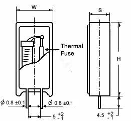
| Type | Dimensions (mm) | |||||
|---|---|---|---|---|---|---|
| W ± 1 | D ± 1 | H ± 1 | RM +2/-1 | h | Φ d1 | |
| RXF/RYF-5 | 13 | 9 | 25 | 5 | 4.5 | 0.8±0.1 |
| RXF/RYF-7 | 13 | 9 | 38 | 5 | 4.5 | 0.8±0.1 |
| RXF/RYF-10 | 16 | 12 | 35 | 7.5 | 4.5 | 0.8±0.1 |
Characteristics
| Temperature Fuse Resistor | Rated Power At 70°C(W) | Resistance Range | Tolerance | |||||||
|---|---|---|---|---|---|---|---|---|---|---|
| Mark | Fusing Temperature(°C) | Standard Current(A) | Standard Voltage(V) | 5 | 7 | 10 | Wirewound RXF | Metal Oxide RYF | Wirewound RXF | Metal Oxide RYF |
| A | 109 +1/-3 | 10 | 250 | 1.2 | 1.4 | 2.0 | ||||
| B | 129±4 | 10 | 250 | 1.6 | 2.0 | 2.5 | ||||
| C | 152±4 | 10 | 250 | 1.6 | 2.0 | 2.5 | J | |||
| D | 188 +2/-1 | 10 | 250 | 2.0 | 2.4 | 3.5 | (±5%) | J | ||
| E | 226 +1/-3 | 10 | 250 | 2.0 | 2.4 | 3.5 | 1~100Ω | 110Ω~10KΩ | (±5%) | |
| F | 95 +3/0 | 2 | 250 | 0.8 | 1.2 | K | ||||
| G | 110±4 | 2 | 250 | 1.2 | 1.4 | (±10%) | ||||
| H | 126±4 | 2 | 250 | 1.4 | 1.6 | |||||
| N | 130±4 | 2 | 250 | 1.6 | 2.0 | |||||
| M | 145±4 | 2 | 250 | 2.1 | 2.4 | |||||
Please consult factory for special fusing conditions not shown
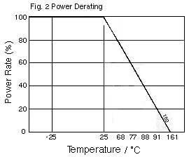
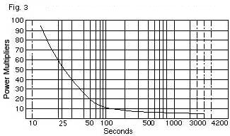
| Derating Curve | Blowtime Curve at Elevated Wattages |
 |
 |
|
To find the fusing time at an elevated wattage, multiply the resistor's rated wattage @ 25 °C by the power multiplier. (fig. 3)
|
|
Two Factors to consider when choosing a thermal fuse resistor: |
||||||||||||||||||||||||
| Ordering Information: | ||||||||||||||||||||||||
| Example: 129°C Blow Time 10 ohms 5% 10AMP Blow Time | ||||||||||||||||||||||||
| RXF5 |
B BLOW TEMP °C |
1ORO RESISTANCE |
J TOLERANCE |
10 BLOW AMPS |
||||||||||||||||||||
| TYPE |
|
|
4 DIGITS USE R FOR DECIMAL |
J = 5% K = 10% |
2 = 2amps 10 = 10amps |
||||||||||||||||||||
| home page | product guide |
TO ORDER PRODUCTS E mail: microohm@mail.com Call Toll Free: 1-800-845-5167 |