

Feature
- EIA standard color coding
- Flame retardant type available
- Low noise & voltage coefficient
- Low temperature coefficient range
- Multiple epoxy coating on vacuum-deposited metal film provides superior moisture protection
- Nichrome resistive element provides stable performance in various environments
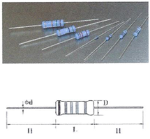
| Part No. | Type | Power Rating at 70°C | Dimension(mm) | |||
|---|---|---|---|---|---|---|
| D Max. | L Max. | d±0.05 | H±3 | |||
| Normal Size | ||||||
| MFR0W8 | MF-12 | 1/8W | 1.9 | 3.5 | 0.45 | 28 |
| MFR0W4 | MF-25 | 1/4W | 2.5 | 6.8 | 0.54 | 28 |
| MFR0W2 | MF-50 | 1/2W | 3.5 | 10 | 0.54 | 28 |
| MFR01W | MF-100 | 1W | 5 | 12 | 0.65 | 28 |
| MFR02W | MF-200 | 2W | 5.5 | 16 | 0.70 | 28 |
| MFR03W | MF-300 | 3W | 6.5 | 17.5 | 0.75 | 28 |
| Small Size & Extra Small Size | ||||||
| MFR0S4 | MF-25-S | 1/4W | 2 | 3.5 | 0.45 | 28 |
| MFR004 | MF-40-SS | 0.4W | 2 | 3.5 | 0.45 | 28 |
| MFR0U2 | MF-50-SS | 1/2W | 2.7 | 6.8 | 0.54 | 28 |
| MFR0S2 | MF-50-S | 1/2W | 3 | 9 | 0.54 | 28 |
| MFR006 | MF-60-S | 0.6W | 2.7 | 6.8 | 0.54 | 28 |
Standard Non-flammable coating for Small size type (except MF-50-S).
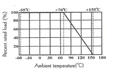
Derating Curve
| Part No. | Type | Dielectric Withstanding Voltage | Max. Working Voltage | Max. Overload Voltage | Standard Order | Special Order | ||||
|---|---|---|---|---|---|---|---|---|---|---|
| Tolerance | TCR | Value Range | Tolerance | TCR | Value Range | |||||
| MFR0W8 | MF-12 | 400V | 200V | 400V | ±1% | ±50 | 10Ω-1MΩ | ±0.25% | ±15 | 51.1Ω~200KΩ |
| MFR0S4 | MF-25-S | 200V | 200V | 400V | ±2% | ±100 | 10Ω-1MΩ | ±0.5% | ±25 | 51.1Ω~511KΩ |
| MFR004 | MF-40-SS | ±5% | ±200 | 1Ω-1MΩ | ±0.5% | ±50 | 51.1Ω~511KΩ | |||
| MFR0W4 | MF-25 | 500V | 250V | 500V | ±1% | ±50 | 10Ω-1MΩ | ±0.1% | ±15 | 10Ω~1MΩ |
| MFR0U2 | MF-50-SS | 250V | 250V | 500V | ±2% | ±100 | 1Ω-1MΩ | ±0.25% | ±25 | 10Ω~1MΩ |
| MFR006 | MF-60-S | ±5% | ±200 | 1Ω-1MΩ | ±0.5% | ±50 | 10Ω~1MΩ | |||
| MFR0S2 MFR0W2 |
MF-50-S MF-50 |
700V | 350V | 700V | ±1% | ±50 | 10Ω-1MΩ | ±0.1% | ±15 | 100Ω~330KΩ |
| ±2% | ±100 | 10Ω-1MΩ | ±0.25% | ±25 | 51.1Ω~511KΩ | |||||
| ±5% | ±200 | 1Ω-1MΩ | ±0.5% | ±50 | 10Ω~1MΩ | |||||
| MFR01W | MF-100 | 1000V | 500V | 1000V | ±1% | ±50 | 51.1Ω-1MΩ | ±0.1% | ±15 | 100Ω~330KΩ |
| MFR02W | MF-200 | ±2% | ±100 | 51.1Ω-1MΩ | ±0.25% | ±25 | 51.1Ω~511KΩ | |||
| MFR03W | MF-300 | ±5% | ±200 | 1Ω-1MΩ | ±0.5% | ±50 | 51.1Ω~1MΩ | |||
Performance Specification
| Temperature coefficient | refer to P.20 |
| Short-time overload | ΔR/R ≤ ±(0.5%+0.05Ω), with no evidence of mechanical damage |
| Dielectric withstanding voltage | With no evidence of flashover, mechanical damage, arcing or insulation breakdown |
| Pulse overload | ΔR/R ≤ ±(1%+0.05Ω), with no evidence of mechanical damage |
| Terminal strength | No evidence of mechanical damage |
| Resistance to solering heat | ΔR/R ≤ ±(1%+0.05Ω), with no evidence of mechanical damage |
| Resistance to solvent | No deterioration of protective coating and marking |
| Temperature cycling | ΔR/R ≤ ±(1%+0.05Ω), with no evidence of mechanical damage |
| Load life in humidity | Normal type: ΔR/R ≤ ±1.5%, Flame retardant type: ΔR/R ≤ ±5%. |
| Load life | Normal type: ΔR/R ≤ ±1.5%, Flame retardant type: ΔR/R ≤ ±5%. |
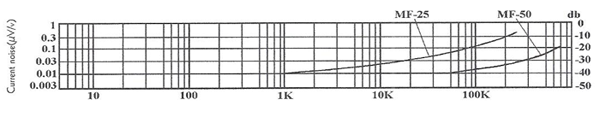
Current Noise Level
Ordering Procedure (Example: MFR 1/8W 1% 50PPM 47.5KΩ T/R-5000)
MFR
- Product Type:
-
- MFR = Metal Film Fixed Resistors
0
- Special Feature:
-
- 0 = Standard
- F = Flame retardant
- I = Non-Inductive
- C = Flammable type
W8
- Wattage:
-
- Normal size:
- WG = 1/16W
- W8 = 1/8W
- W6 = 1/6W
- W4 = 1/4W
- W2 = 1/2W
- 1W = 1W
- 2W = 2W
- 3W = 3W
- Small size:
- S4 = 1/4W-S
- S2 = 1/2W-S
- 06 = 0.6W-S
- Extra small size:
- U2 = 1/2W-SS
- 04 = 0.4W-SS
F
- Tolerance (&TCR):
-
- B=±0.1% 15 PPM
- C=±0.25% 25 PPM
- D=±0.5% 50 PPM
- F=±1% 50 PPM
- G=±2% 100 PPM
- J=±5% 200 PPM
- For special tolerance-TCR requirement, please indiciate in the purchasing order.
- Example: ±1% 15PPM
4752
- Resistance Value
-
- 5% (E-24 series):
- the 1st digit is "0", the 2nd & 3rd digits are for the significant figures of the resistance and the 4th indicate the numbers of zeros following.
- 1% or less & 2% (E-96 series):
- the 1st to 3rd digits are for the significant figures of the resistance and the 4th indicate the numbers of zeros following.
T
- Packing Type:
-
- A = Tape/Box
- T = Tape/Reel
- B = Bulk/Box
- P = Tape/Box of PT-26 product
5
- Packing Qty.:
-
- 1 = 1,000pcs
- 2 = 2,000pcs
- 3 = 3,000pcs
- 4 = 4,000pcs
- 5 = 5,000pcs
- A = 500pcs
- B = 2,500pcs
- 0 = Bulk/Box
0
- Additional Information:
-
- 0 = NIL